Paya Lebar Crash Avoidance Project

Wingtip Proximity Sensor
Overview of Project
The main objective of this project is to reduce the likelihood of aircraft-ground obstacle collisions during forward or reverse towing operations by mounting a pair of wingtip proximity sensors on each side of the wingtip, which assist in alerting the user about any incoming objects through the use of visual and audio indicators.
In total, there are 6 light emitting diodes (LEDs) that are soldered onto the sensor board to indicate the distance of the measured object (2x Red LED, 2x Amber LED, 2x Green LED). Furthermore, on each side of the Wingtip Proximity Sensor, there are 3 switches to toggle the aircraft mode (F15 or F16), turning the scanning mode on or off, and turning the system on or off.
It also helps to alleviate manpower constraints because a ground crew is no longer required to stand on each side of the aircraft to look out for any ground obstacles during towing operations, allowing them to focus on other tasks. Furthermore, the wingtip proximity sensor can also provide more accurate readings and more precise alerts since factors such as parallax error can influence the ground crew’s judgement during forward or reverse towing operations.
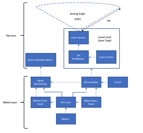
Block Diagram of Wingtip Proximity Sensor
Each wingtip proximity sensor consists of 12 AFBR-S50MV85I time-of-flight sensors which in total are capable of scanning 120° horizontally and 5° vertically. Additionally, a dedicated mounting arm is also provided for each kind of aircraft (F15 or F16) which will allow for quick attachment and detachment capabilities while causing minimal foreign object debris.
The threshold values at which the red, amber, and green LEDs are triggered will vary depending on the size of the aircraft. For instance, the amber LED will be lit between 1 and 2 meters for the F15 aircraft and between 1 and 3 meters for the F16 aircraft. Furthermore, the buzzer will beep faster as the aircraft approaches the object.
My Roles and Responsibilities
My roles include testing, troubleshooting, and repairing the malfunctioning circuit boards that will be used in this project which include the sensor board, central processing unit (CPU) interface and the power supply board to ensure that they are functioning before they are sent for assembly. Aside from testing the various circuit boards, I am also responsible for developing the testing procedures to test the functionality of the various circuit boards.
My job roles also include assisting my colleagues who are on the assembly team crimp the relimate connectors that are used to connect the sensor board, CPU interface, and the power supply board based on the schematic, as well as solder the switches that will be used to toggle the aircraft mode (F15 or F16), turn the scanning mode on or off, and turn the system on or off based on the schematic.
I am also part of the software development team responsible for the software development of the system, and my job roles include testing, debugging, and optimizing the system to improve its effectiveness and reliability while also implementing new features to improve the usability of the system, which requires me to have a solid foundation in C and C# along with strong analytical and problem-solving abilities.
My Contributions
Throughout my internship, I have helped to test every component of the wingtip proximity sensor, which includes the AFBR-S50MV85I time-of-flight sensors, sensor board, CPU interface and the power supply board.
I have also crimped and assembled all the 10-way, 8-way, 6-way, 4-way and 3-way relimate connectors that will be used to connect the sensor board, CPU board, power supply board and the LED indicator board.
I have also helped to brainstorm and implement new features to update the old software so as to improve the overall user experience.
The following describes the features that I have help to implement into the software::
-
The red LED on the Wingtip Proximity Sensor will blink to warn users that the scanning switch is switched off.
-
Battery warning system where it would warn the user if the current battery percentage of the unit is low.
-
Improving the responsiveness of the software by reducing the time it takes for the LED to return to green after the object moves away.
-
The buzzer on the Wingtip Proximity Sensor will beep faster whenever the aircraft approaches the object.
-
A program that will help to detect dead sensors whenever the scanning switch is switched off. Furthermore, the red LED on the Wingtip Proximity Sensor will blink faster is there is a dead sensor.
Real world application of industry domain knowledge and skills in the workplace
I was able to understand and analyze the truth tables provided in the datasheets of each IC using the knowledge imparted to me by Mr. Koh in Digital Fundamentals (DIGF) and Mrs. Tan in Applied Digital Electronics (ADEL). For example, a 74HC138 3-to-8-line decoder demultiplexer was used in the sensor board to select the 12 different sensors, which was one of the various ICs that we were taught about in ADEL.
We were also introduced to Tina in DIGF and ADEL, a simulation software which allowed me to explore different analogue and digital components of DIGF and ADEL, such as the 74HC138 3-to-8-line decoder demultiplexer.
Problem-solving in the workplace
Over the course of this internship, I have realized how important it is to have strong problem-solving abilities, especially for engineering-related professions where we encounter a wide range of issues on a daily basis.
Developing and building a test jig to improve the testing efficiency

Schematic of Testing Jig
Initially, we used a digital multi-meter to check the voltage of each pin, but it was inefficient and time-consuming because we had to test the connections for the 10-pin housing for all 12 sensors. Additionally, because the probes on the digital multi-meter were rather large, it was quite inaccurate.
As a result, I wanted to build a test jig that would be mounted onto the sensor housing. The testing jig would have LEDs on it to indicate the voltage at the various pins. For example, the LED will not turn on if the voltage at the pins is 0V, but it will turn on if the voltage is 5V. Furthermore, I also added a button to simulate the interrupt request. When the button is not pressed, the voltage at the CPU's IRQ is 5V, but when the button is pressed, the voltage at the CPU's IRQ is 0V.

Testing Jig
Implementing a hysteresis loop to compensate for fluctuations in the sensor's measured values
To improve the usability of the Wingtip Proximity Sensor, I added a feature that increases the buzzer’s buzzing frequency as the object approaches the sensor. As a result, the buzzer would beep more quickly when the object is closer the sensor. However, after some testing, I discovered that the beeping sound was rather unstable since noise in the environment was causing the measured readings from the sensor to fluctuate.
Using a hysteresis loop, we are able to control the outputs such that at the threshold value, even if the measured data fluctuates, it will not change state until it reaches the end of the hysteresis dead band.

Diagram illustrating the updated software architecture, which utilizes a
hysteresis control loop to improve the stability of the beeping sound at the threshold point
Learning Points
I learned how to monitor the discharging and charging performance of the Powerizer 3.7V 5Ah lithium-ion polymer battery pack and calibrate the fuel gauge level on the status indication board of the Wingtip Proximity Sensor as shown using the DS2788K evaluation software kit.
To calibrate the Powerizer 3.7V 5Ah lithium-ion polymer battery pack, we would need to fully charge it using a power supply that is operating in the constant current mode. Additionally, a forward biased diode is used to ensure that there is no current backflow from the battery that might damage the power supply. Furthermore, we must regularly check the battery voltage to ensure that it stays below 4.2V because the power source will continue to charge the battery even after its maximum capacity has been achieved, which may shorten the lifespan of the battery pack.
After the battery has reach its maximum capacity, we will use the DS2788K evaluation software kit to set the accumulated charge register, which is the current battery level of the battery pack to 5000 mAhr. The battery will then be discharged, and we will then measure the time it takes for the battery to completely discharge. We will then repeat the same process over a period of a month to ensure sure that the battery's performance remains relatively consistent over time.
Moreover, I learned how to calibrate the AFBR-S50MV85I time-of-flight sensor using the AFBR-S50 explorer to offset the crosstalk, which are unwanted signals introduced by interfering elements. I also understood the importance of calibrating the sensors at different times of the day to ensure that they can consistently operate and accurately determine an object's distance under a wide variety of environments.
To calibrate the sensor, we cover the AFBR-S50MV85I time-of-flight sensor with a black piece of rubber or fabric to simulate infinity before performing the crosstalk calibration sequence in order to obtain Xtalk (shaded). Thereafter, without covering the sensor, we perform the crosstalk calibration sequence after placing an object that is around 3 to 4 metres away from the sensor to obtain Xtalk (w/o coverglass). Lastly, we perform the crosstalk calibration sequence while using the protective glass or film in order to obtain Xtalk (with coverglass).
We then compile the crosstalk values into an excel sheet to obtain the final crosstalk value, or Xtalk (total) using the equation - Xtalk(total) = Xtalk(shaded) - Xtalk(w/o coverglass) + Xtalk(with coverglass), and we import the final crosstalk value back into the Xtalk vector table of the AFBR-S50 Explorer to help compensate for any electrical crosstalk that occurs due the circuit board as well as optical crosstalk that may occur when a protective glass/film is used to waterproof and protect the AFBR-S50MV85I time-of-flight sensors from any water damage.
I learned the importance of writing readable code as it will help other software developers in the future modify and understand the code with ease. Writing readable code may be done in a variety of ways. For instance, we can use comments to describe the purpose of each block of code. Additionally, the names of the variables and arrays must be clear and descriptive of their functions.